Previously I discussed the issues involved with determining how many, and what types, of cables should be run to each faceplate (also known as the Work Area Information Outlet, WAIO). The cost of installing telecom cables has three components: (1) the cost of the cable, (2) the cost of the labor to install the cables, and (3) the cost of terminating, testing and tagging the cables. In almost all cases the labor cost will be the most expensive component. The labor cost will also show little change regardless of the number of cables installed. In other words, the labor cost to install one telecom cable to a WAIO is almost the same as the cost to install three or four cables. There will be a corresponding increase in the cost of the material (cable) and the cost of terminating, testing and tagging the cables, but that is a relatively small increase compared to the labor.
In a previous article I also recommended standardizing the design by running an identical cable set to each WAIO (for example, three Category 5e or 6, Unshielded Twisted-Pair cables). This makes cable plant administration easier since every faceplate is identical. What about those locations where more than three cable are required? My suggestion was to install another WAIO in that location equipped with a standard cable set.
Although these design principles work well for new construction or when renovating a floor, they do not help when an existing location needs one or two more data jacks. In fact, since the installation crew must work in an occupied area, it is usually more expensive to add cables after the fact.
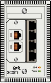
Enter the NJ-100 from 3Com Corporation (www.3com.com). This unique product ($140 list price) can be used effectively in both new construction and retrofit applications where more connectivity is required. The NJ-100 incorporates electronic circuitry (normally contained in the network Ethernet switches located in telecommunications rooms) into the WAIO which effectively allows one data cable to do the work of four.
The NJ-100 has two sections. On the left are two positions for optional modular connectors for conventional telephone services or other non-data applications. On the right are four data jacks that connect to the Ethernet switch built into the RJ-100. On the rear of the NJ-100 a single UTP cable transmits data between the NJ-100 Ethernet switch and the equipment in the telecommunications room.
Power for the electronics contained in the NJ-100 can be provided from a central source such as a power supply located in the telecommunications room or locally from a plug-in power module. In addition to powering the NJ-100 itself, the NJ-100 contains a Dual Inline Package (DIP) switch, which can be used, for example, to configure one of the data jacks to supply power to a Voice-over-Internet-Protocol (VoIP) telephone set. By changing the settings on the DIP switch, power can be provided to the data jack on the same physical pair of wires used for Ethernet transmission (Cisco's implementation; both 24 and 48 volt operation is supported) or power can be supplied over a separate pair of wires (IEEE Standard 802.3af).
So now when you need a few more data connections at a WAIO, you don't have to always pull more cables. Take an existing data cable, connect it to the NJ-100 and, bingo, you now have four 10/100 Mbps auto-negotiating data connections.
Issues with the NJ-100 are minor, but they do need to be considered.
The present NJ-100 is unmanaged and does not support SNMP or other network management protocols, but I don't believe that is a big issue given its function and position in the network architecture.
The NJ-100 is thick (0.80") and can dissipate as much as 13 watts when supplying an Ethernet-powered device. It is also
One potential serious issue is the method of connecting the NJ-100 to the horizontal cable at the WAIO (horizontal cables are the cables that run between the telecommunications room and the WAIO). The current design of the NJ-100 uses an 8-pin modular jack (commonly called an RJ-45) for connecting to the horizontal cable. This requires either terminating the horizontal cable with an 8-pin modular plug or using a very short RJ-45-plug-to-RJ-45-plug jumper. Never method complies with EIA/TIA Standard 568B and, in theory, this method of connecting the NJ-100 to horizontal cabling could introduce network throughput problems.
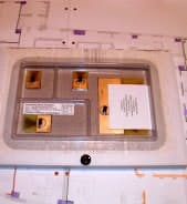
An array of ceiling tile antennas can be used exclusively or they can be used in conjunction with conventional antennas to provide coverage in corridors and circulation areas. Armstrong has partnered with firms that can provide complete systems engineering and installation of radio equipment including building-wide cellular telephone coverage.
Putting WLAN antennas in the ceiling can ensure a line-of-sight connection between the wireless networking adapter in the desktop or laptop PC and the antenna. A line-of-sight connection maximizes the signal-to-noise ratio in the transmission path, which, in turn, allows the wireless connection to operate at the highest possible speed (as the signal-to-noise ratio gets worse, the transmission speed automatically slows down). Many factors determine the useable range for a given antenna, but a range of 100 feet in a typical office environment is not unreasonable for 802.11b (11 Mbps). However, some recent tests have indicated that 802.11a (54 Mbps) WLAN antennas may have a range of only 25 feet at 54 Mbps.Ernest Schirmer is a Principal with the Technical Design Alliance in Lawrenceville, New Jersey. For more information, please visit www.interior-technology.net or email [email protected].


